


Within the arsenal of lights provided by game engines, the most popular are punctual lights such as point, spot or directional because they are cheap. On the other end, area lights have recently produced incredible techniques such as Linearly Transformed Cosines and other analytic approximations. I want to talk about the line light.
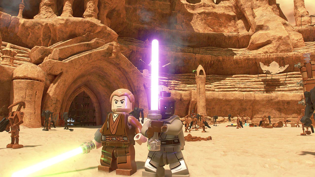
Update [04/09/2020] When I originally wrote the article there were no public images showing Jedi or lightsabers so I couldn’t make the connection (though a clever reader could have concluded what they might be for!) I can finally show this work off as it’s meant to be. You can also watch a gameplay trailer here.
In Unreal Engine 4, modifying ‘Source Length’ on a point light elongates it as described in this paper. It spreads the intensity along the length so a longer light becomes perceptually dimmer. Frostbite also has tube lights, a complex implementation of the analytical illuminance emitted by a cylinder and two spheres. Unity includes tube lights as well in their HD Render Pipeline (thanks Eric Heitz and Evegenii Golubev for pointing it out) based on their LTC theory, which you can find a great explanation and demos for here. Guerrilla Games’ Decima Engine has elongated quad lights using an approach for which they have a very attractive and thorough explanation in GPU Pro 5’s chapter II.1, Physically Based Area Lights. This is what I adapted to line lights.
Most Representative Point
The method is inspired by Montecarlo Importance Sampling, where a biasing function modifies uniform input samples into samples that are non-uniformly distributed according to the shape of the function. The typical scenario in rendering is to efficiently sample a specular BRDF, where uniform samples produce suboptimal results at low roughnesses. MRP takes the idea to the extreme, using a single most important sample. Past literature explores this idea in detail here and here. The core of the algorithm is to find a point that provides the greatest contribution and treat that as a point light, leveraging existing BRDF and falloff functions. I imagine a light that “travels” with the shaded pixel bound by some rules, the result looking like a light with some dimensionality. All the above engines use this idea in varying forms. We’ll describe the line light as a segment formed by points A and B, and globally define P as the shading point.
1 2 3 | float3 PA = A - P; float3 PB = B - P; float3 AB = B - A; |
Diffuse
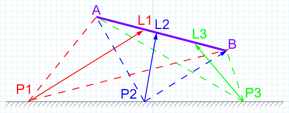
A key insight for me was discovering that there are actually two most representative points: diffuse and specular. Each point does its part and after evaluating the BRDF we add their contributions together. According to Guerrilla’s paper, the most representative point for a diffuse BRDF is the intersection point between two vectors:
- The half vector formed by the vector from P to A and the vector from P to B
- The vector defined by the line direction AB
Here I have shown three shading points P1-3, to illustrate how the position of the virtual point light L1-3 moves with the shading point. The moment L reaches A or B, it won’t be able to travel further and stop at that point, which we’ll perceive as a segment.
There are two main approaches to compute L, intersection and geometric. I will briefly mention both as it was my original thought process. For the intersection approach we first compute H, the half vector between PA and PB. We then find the intersection point between vector AB and H. The derivation and proof for a robust algorithm to do this is shown in Real Time Rendering, Third Edition, p.782, or a small excerpt formula here. In code:
1 2 3 4 5 6 7 8 9 | float3 H = normalize(PA) + normalize(PB); // Find half vector float3 perpendicularVector = cross(H, AB); // Find vector perpendicular to both H and AB (would intersect both lines) float3x3 m = float3x3(PA, AB, perpendicularVector); // Find intersection between half vector and line vector. There is a guaranteed intersection by construction float s = determinant(m) / dot(perpendicularVector, perpendicularVector); float3 diffuseMostRepresentativePoint = P + H * s; |
This works and is robust but expensive, so we resort to our knowledge of geometry. The half vector is what is called the bisector of an angle, i.e. it cuts the angle exactly in half. The angle bisector theorem says that there is a proportion between the lengths a and b of the segments that form the angle and the lengths x and y of the two segments that the intersection produces, more specifically
Calculating the length of x would allow us to simply offset point A using vector AB to get to the desired point, which is much more efficient. In code:
1 2 3 4 5 6 7 8 | float a = length(PA); float b = length(PB); // Bisector theorem states that a / b = x / y, where c = x + y = length(AB) // Therefore x = c * a / (b + a). Note that c cancels out when normalizing AB float x = a / (b + a); float3 diffuseMostRepresentativePoint = A + AB * x; |
Specular
The most significant specular contribution from a light is going to be around the reflection vector. If we can find the point on the line that is closest to the vector we can use that as our specular point light. In the following diagram we can see the reflection vector R from the camera along the normal N. From that ray we can calculate the closest point on segment AB to R.
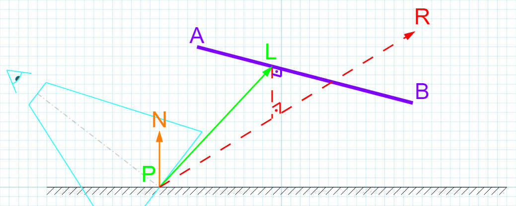
For this calculation I followed the derivation here which is explained in a lot of detail. My solution has assumed that the reflection vector is normalized and therefore the dot product with itself is 1.
1 2 3 4 5 6 7 8 | float3 R = reflectionVector; // If R is normalized, dot(R, R) = 1 and can be optimized away float t_num = dot(R, PA) * dot(AB, R) - dot(AB, PA); float t_denom = dot(AB, AB) - dot(AB, R) * dot(AB, R); t = saturate(t_num / t_denom); float3 specularMostRepresentativePoint = A + AB * t; |
Horizon Handling
Up to now the algorithm works pretty well but breaks down when the segment intersects the plane defined by the shaded pixel and its normal vector, because it can end up selecting a point behind the plane that doesn’t represent the light. The solution is to determine the segment-plane intersection point, and limit the points A or B (depending on the case) to that point. We effectively only consider the segment that is on the positive side of the plane, and do our calculations as described before.
1 2 3 4 5 6 7 8 9 10 11 12 13 14 15 16 17 18 19 20 | float3 N = normalVector; // If points are on opposite sides, guaranteed intersection if(dot(PA, N) > 0.0 != dot(PB, N) > 0.0) { float t = -dot(PA, N) / dot(AB, N); float3 intersectionPoint = A + t * AB; if (dot(PA, N) > 0.0) { B = intersectionPoint; PB = B - P; } else { A = intersectionPoint; PA = A - P; } AB = B - A; } |
Light Textures
Typically, lights can have projected textures that tint the light. In line lights we might want to use a cylindrical texture surrounding the light so the correct vector to sample such a texture is neither the one used for diffuse nor the one used for specular, but rather a vector perpendicular to the line that passes through the shaded point. Essentially, we need to calculate the closest point from the shaded pixel to the line light, and use that to sample the texture.
An alternative is to use a cubemap and treat it as if it was a point light. Simply calculate the center of the segment (before horizon handling) and get vector from shading point to center, and then use that as the sampling vector for the cubemap.
Tube Light Extension
If you wanted to turn this into an actual tube light, a simple approach is to intersect the light with a cylinder of radius R. If we already have the closest point to the line (or we can calculate it in the same way as the closest point to the segment) we can compute, using similar triangles, a distance along the vector we use for diffuse or specular, to obtain a new point on the surface of the light. To account for points on the inside of the light, we must clamp the distance to the length between the shading point and the point on the light, or we risk selecting a point behind the surface. What this means is that for all points within the surface of the tube we’ll get the maximum intensity.
Shadow Mapping
For shadow mapping there is a simple option which is to treat it like a point light, and make shadows emanate from the center, using a cubemap or dual paraboloid which are popular shadowing methods. This is what Unreal Engine does.
The other option is to create a custom shadow projection for the light, which would probably be cylindrical with some special treatment for the caps. Neither MRP is useful for the sampling so the closest vector to the shading point would probably be the most adequate. I have not implemented this so this part is theoretical only.
 Shadertoy
If some of the above did not make sense to you, open the shadertoy implementation and hack away. You’ll probably learn a lot that way too! I’ve not implemented the tube light extension or the shadow mapping in the shadertoy.